Incoming power from a fused disconnect goes to the pressure switch's line terminals, marked L1 and L2. The motor leads go to the load terminals, often the outer pair. The ground wire goes to the green ground screw. A 2-wire submersible runs from the switch straight to the motor, while a 3-wire submersible goes through its control box. Adjust pressures with the large nut, which moves cut-in and cut-off together.
What the switch does
A well pump pressure switch senses water pressure through a small fitting at its base. When pressure falls to the cut-in setting, its contacts close and power flows to the motor. When pressure rises to the cut-off setting, the contacts open and the motor stops. Common settings are 20/40, 30/50 and 40/60 PSI. Telemecanique's 9013FSG2J24, for example, is a 40/60 PSI switch with an adjustable differential, a diaphragm actuator and a 1/4 in NPSF pressure connection.
The switch breaks both power legs at once on 230 V systems. Its data sheet lists double-pole, double-break contacts and four terminals, which is why these switches have two pairs of screws inside the cover. The motor rating matters too: the same switch is rated for 1-1/2 HP at 115 V and 2 HP at 230 V single phase.
| Item | Rating |
|---|---|
| Setting | 40-60 PSI, adjustable differential |
| Contacts | 2 NC, snap action, DPST-DB |
| Terminals | 4, screw clamp up to 10 AWG |
| Pressure connection | 1/4 in NPSF internal |
| Motor rating, single phase | 1.5 hp at 115 V AC; 2 hp at 230 V AC |
| Electrical durability | 100,000 cycles |
Line, load and ground: the basic wiring
Red Lion's jet pump manual states the rule simply: connect the power lines to the pressure switch terminals marked L1 and L2, and the motor to the load side. Its wiring diagram shows the power supply on the line terminals and the motor leads on the remaining pair. Wayne's SWS diagram shows the same arrangement, with the line terminals marked L1 and L2, the motor beside them, and a single green ground screw marked GRD under the switch cover.
Grounding is not optional. Wayne says there is only one proper ground terminal and the ground conductor must be no smaller than the circuit conductors; it also notes a metal well casing or water pipe at least 10 ft long makes the best ground electrode. Flotec says to connect the ground wire to an approved ground first, never to a gas line. Red Lion requires a GFCI on its jet pumps and a fused disconnect in the line.
- Turn off the breaker and lock out the disconnect before opening the switch cover.
- Bring the supply cable through a cable entry into the switch.
- Connect the supply conductors to the line terminals L1 and L2.
- Connect the motor leads to the load terminals.
- Attach both ground wires to the green ground screw.
- Replace the cover before restoring power.
115 V or 230 V
Many jet pump motors are dual voltage. Wayne's SWS pumps ship set to 115 V and can be switched to 230 V with a selector inside the motor's terminal cover. Red Lion's RJS pumps use a black voltage change device on the terminal board that points to 115 or 230. The motor setting must match the supply, or the motor will hum and fail to start; Wayne lists a mismatch between line voltage and the selector as the first cause of a motor that hums but will not run.
At 230 V both supply wires are hot, so both line terminals carry power. At 115 V one is neutral. In either case the switch opens both legs. Change the motor selector only with power off, and confirm the supply voltage with a meter before you start.
2-wire vs 3-wire submersible pumps
Deep well submersibles come in two wiring types. Flotec says a 2-wire motor has two black power wires and a green ground, needs no control box, and runs from the pressure switch directly to the motor. The Flotec FP2211 is one example.
A 3-wire motor adds a start circuit housed in a control box at the surface. The switch's load side feeds the control box, and the control box feeds the motor by colour: yellow to Y, red to R, black to B. Flotec warns that a 3-wire pump will not run without its control box and that running it without one burns out the motor, and asks that the box be mounted upright so its relay works. For motors of 1-1/2 HP and up, Flotec calls for a magnetic starter to protect the pressure switch contacts. The Red Lion RL12G05-3W2V is a 3-wire pump.
Adjusting cut-in and cut-off
Pentair's adjustment sheet covers the common one-post and two-post switches. Turning the large nut clockwise raises both cut-in and cut-off by 2-1/2 PSI per full turn, keeping a 20 PSI differential between them. On two-post switches, the small nut raises only the cut-off. Turn either nut counter-clockwise to lower pressure.
Stay within limits. Pentair says never to set cut-in below 20 PSI or cut-off above 60 PSI, and to keep cut-off at least 5 PSI below the pump's dead-head pressure, or the pump may never shut off. After any change, reset the tank precharge to 2 PSI below the new cut-in.
| Setting | Rule |
|---|---|
| Cut-off | At least 5 PSI below dead-head pressure |
| Cut-in | Typically 20 PSI below cut-off |
| Tank precharge | 2 PSI below cut-in |
| Adjustment rate | 2-1/2 PSI per full turn of the main nut |
Figures: Pentair instructions for adjusting well pump pressure switches U80-129.
Wiring faults to look for
Red Lion's troubleshooting guide lists no power to the pressure switch from blown fuses, open switches or loose connections as the first reason a jet pump motor will not start. Burned or pitted contacts, a loose terminal or a cracked wire under the cover produce the same symptom. Wayne lists inadequate wiring among causes of a humming motor and repeated overload trips.
If the switch is worn, replace it with one of the same range and rating. The Telemecanique 9013FSG2J24 and Square D FSG2J21CP cover the two most common ranges.
Common mistakes
- Connecting the supply to the load terminals so the motor side is always live.
- Leaving the motor voltage selector on 115 V when the supply is 230 V.
- Wiring a 3-wire submersible straight to the switch without its control box.
- Skipping the ground or grounding to a gas line.
- Setting cut-off higher than the pump can reach.
Products that fit
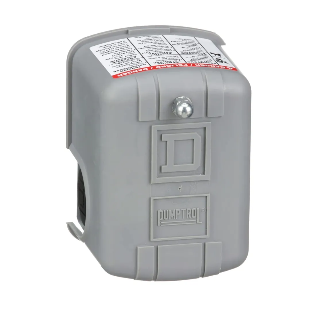
Square D 9013FSG2J24 40/60 PSI Pressure Switch
40/60 PSI double-pole pressure switch with four terminals and an adjustable differential.
Square D FSG2J21CP 30/50 PSI Pressure Switch
30/50 PSI pressure switch for systems set at the common jet pump range.

Flotec FP2211 115 V Deep Well Submersible Pump
2-wire submersible that wires from the switch straight to the motor.

Red Lion RL12G05-3W2V Deep Well Submersible Pump
3-wire submersible that needs its control box between switch and motor.
Questions readers ask
Which side of a pressure switch is line and which is load?
The terminals marked L1 and L2 take incoming power, as Red Lion and Wayne's diagrams show. The other pair, often the outer terminals, goes to the motor. Check the label inside your switch cover, because layouts vary by brand.
Can I wire a pressure switch myself?
Makers say an electrician should do it and that the work must follow the National Electrical Code and local rules. It involves line voltage, grounding and a fused disconnect, so a licensed electrician is the safe choice.
Does a 2-wire submersible need a control box?
No. Flotec says 2-wire motors run from the pressure switch directly to the motor. Only 3-wire motors need a control box, and they will burn out without one. Check the motor label to be sure.
How do I raise the pressure on my well switch?
Turn the large nut clockwise; Pentair says each full turn raises both cut-in and cut-off by 2-1/2 PSI. Keep cut-off at or below 60 PSI and reset the tank precharge afterwards.